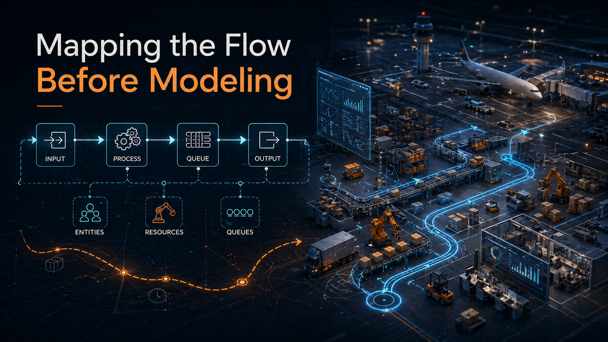
Mapping the Flow Before Modeling
Map the flow before building the model. This Simlog explains how value stream thinking, entities, resources, queues, and Lean concepts help turn process understanding into reliable simulation logic.
In the previous Simlog, I argued that most simulation failures do not come from bad logic. They come from modeling the wrong system.
That leads to the next question:
Once we know the real system we are modeling, how do we understand it before building the simulation?
The answer is simple, but often skipped:
Map the flow first.
Before we build logic, import layouts, place resources, define schedules, or animate equipment, we need to understand how value moves through the system.
Simulation modeling should not begin with objects.
It should begin with flow.
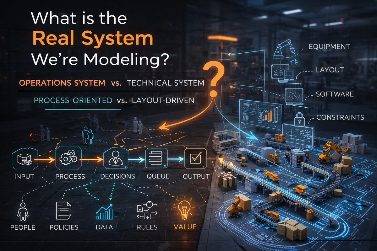
The System Is Not the Layout
A layout tells us where things are located.
A process map tells us what actually happens.
That distinction matters.
A facility layout may show machines, conveyors, docks, gates, rooms, storage areas, or workstations. But it does not automatically explain:
- What enters the system
- What is transformed
- Where work is performed
- Where waiting occurs
- Which resources are required
- Which decisions control routing
- Where variability enters
- Where constraints appear
- What creates value
- What creates delay
A layout is useful.
But it is not enough.
If we start with the layout, we may end up modeling physical space before we understand operational behavior. The result may look realistic, but it may not answer the real business question.
That is why mapping precedes simulation.
Do Not Model Confusion
There is a common trap in simulation projects:
The team does not fully understand the process, so they decide to build a model to understand it.
That can work only if the first phase of modeling is exploratory and disciplined.
But if the team skips mapping and jumps directly into software, they may simply model confusion.
The model becomes a collection of assumptions, guesses, and visual objects.
The better approach is to slow down at the beginning.
- Map the flow.
- Discuss the process.
- Identify the waiting points.
- Challenge the assumptions.
- Ask where value is actually created.
- Ask where the system is unstable.
- Ask where resources are overburdened.
- Then model the system in the software.
Why Mapping Must Come Before Simulation
Mapping before simulation is not extra work.
It is the work that makes simulation meaningful.
Without mapping, the modeler is forced to guess:
- What the process steps are
- Where entities enter and exit
- Which resources are required
- Where queues form
- Which decisions matter
- What variability should be included
- What performance measures are relevant
- What assumptions are being made
That is dangerous.
A model built on unclear process understanding may still run.
It may still produce charts.
It may still generate impressive animation.
But it may not represent the real system.
Worse, it may create false confidence.
Simulation gives numbers. Numbers can look authoritative. But if the underlying process logic is wrong, the results are not reliable.
Mapping reduces that risk.
Value Stream Mapping and Simulation
A value stream map helps us see how value is created, delayed, interrupted, or wasted as something moves through a process.
In Lean thinking, the goal is not simply to describe activity.
The goal is to distinguish between:
- Value-added work
- Necessary but non-value-added work
- Waste
- Waiting
- Rework
- Movement
- Excess inventory
- Overburden
- Variation
This is directly relevant to simulation.
A simulation model is not just a digital version of a facility. It is a decision-support tool. It helps us test how the system behaves under different conditions.
But to simulate behavior, we first need to understand the flow.
A value stream map gives us the first version of that understanding.
It shows the major steps in the process, the handoffs between steps, the queues between activities, the resources required, and the timing assumptions that may later become model inputs.
From Value Stream to Simulation Logic
In simulation modeling, especially discrete-event simulation, we usually need to define several basic elements.
The most important are:
Simulation Element | Practical Meaning |
|---|---|
Entities | The things that move through the system |
Activities | The work or transformation performed |
Resources | The people, equipment, tools, or space required |
Queues | The waiting points between activities |
Routing Rules | The logic that determines where entities go next |
Decision Rules | The policies that control priority, assignment, release, or selection |
Processing Times | How long activities take |
Arrival Patterns | How entities enter the system |
Variability | The uncertainty in timing, demand, availability, or behavior |
These are not software objects first.
They are operational concepts first.
For example:
System | Entity | Resource | Queue |
|---|---|---|---|
Airport turnaround | Aircraft | Gate, crew, equipment | Aircraft waiting for gate or service |
Warehouse | Order or pallet | Picker, forklift, dock door | Orders waiting to be picked or shipped |
Clinic | Patient | Doctor, nurse, room | Patients waiting for care |
Manufacturing line | Part or batch | Machine, operator, fixture | Work-in-process between steps |
The simulation model becomes useful when these elements reflect the actual process.
If they are guessed, misunderstood, or skipped, the model may produce results — but the results may not mean much.
Entities: What Is Flowing?
The first modeling question is not “What object do I place in the software?”
The first question is:
What is flowing through the system?
That flowing item may be physical, informational, or even conceptual.
It could be:
- A product
- A customer
- A patient
- An aircraft
- A vehicle
- A document
- An order
- A service request
- A batch
- A task
This matters because the entity defines the viewpoint of the model.
For example:
If we model aircraft, we see gates, taxiways, crews, fueling, baggage, and delays from the aircraft’s perspective.
If we model passengers, we see check-in, security, walking time, boarding, and missed connections.
Both may involve the same airport.
But they are not the same model.
The entity determines what the model sees.
Resources: What Is Needed to Do the Work?
Resources are the people, equipment, tools, locations, or systems required to perform work.
They are often the source of constraints.
Examples include:
- Operators
- Mechanics
- Nurses
- Forklifts
- Machines
- Gates
- Dock doors
- Inspection stations
- Vehicles
- Software systems
- Work areas
A process step may be simple on paper but constrained in practice because it requires a limited resource.
For example:
A truck may arrive on time, but cannot unload because no dock door is available.
An aircraft may be ready for service, but the ground crew is still assigned elsewhere.
A machine may be idle, but the required operator is not available.
A simulation model must capture these relationships.
Otherwise, it may show unrealistic flow because it ignores the real limiting factors.
Queues: Where the System Reveals Itself
Queues are often the most honest part of an operation.
A queue tells us that something is waiting.
And waiting tells us that flow has been interrupted.
Queues can form because of:
- Limited capacity
- Poor scheduling
- Batch releases
- Resource conflicts
- Long processing times
- Variability
- Rework
- Priority rules
- Unbalanced flow
- Missing information
- Downstream congestion
In many simulation projects, queues are where the real story begins.
A queue is not just a line.
It is evidence.
It tells us where demand, capacity, timing, and policy are misaligned.
That is why process mapping should identify not only the work steps, but also the waiting points between them.
Lean Concepts: Muda, Mura, and Muri
Lean gives us a useful language for understanding process problems before we model them.
Three concepts are especially important:
Lean Concept | Meaning | Simulation Relevance |
|---|---|---|
Muda | Waste | Helps identify non-value-added activity, unnecessary movement, waiting, rework, and excess inventory |
Mura | Unevenness | Helps identify variation, imbalance, irregular arrivals, and unstable workload |
Muri | Overburden | Helps identify overloaded people, machines, equipment, or systems |
These concepts are not abstract theory.
They are practical modeling clues.
Muda: Waste
Muda points us toward activities that consume time or resources without creating value.
In a simulation model, this may appear as:
- Excess travel distance
- Waiting time
- Rework loops
- Unnecessary handling
- Excess inventory
- Idle time caused by poor coordination
- Duplicated work
If the process map reveals large amounts of waste, the simulation should help test how much that waste affects performance.
Mura: Unevenness
Mura is variation or unevenness in the system.
This is one of the main reasons simulation is useful.
Average values hide variation.
A process may look fine on average but fail during peaks, surges, disruptions, or uneven arrivals.
Mura may appear as:
- Irregular demand
- Uneven arrival patterns
- Variable service times
- Shift changes
- Batch releases
- Schedule instability
- Equipment downtime
- Unbalanced workloads
Simulation is especially valuable when the system cannot be understood with averages alone.
Muri: Overburden
Muri occurs when people, machines, or systems are pushed beyond reasonable limits.
In simulation, this often appears as high utilization.
But high utilization is not always good.
A resource operating near 100% utilization has little room to absorb variation. Small disruptions can create long queues, long delays, and unstable performance.
This is where simulation becomes powerful.
It can show that the problem is not simply capacity.
The problem may be overburden, poor allocation, poor timing, or lack of flexibility.
The Process Map Becomes the Model Blueprint
A good process map becomes the first blueprint for the simulation model.
It helps define:
Process Mapping Output | Simulation Modeling Use |
|---|---|
Start and end points | Model boundaries |
Process steps | Activities or process flow logic |
Flow items | Entities |
Workers and equipment | Resources |
Waiting points | Queues |
Decision points | Conditional logic |
Timing estimates | Processing time distributions |
Arrival behavior | Source logic |
Rework loops | Routing logic |
Bottlenecks | Scenario focus |
Performance concerns | Output metrics |
This is why Lean and simulation work well together.
Lean helps us see the process.
Simulation helps us test the behavior of that process under changing conditions.
Lean asks: Where is the waste, unevenness, and overburden?
Simulation asks: What happens if we change the system?
Together, they move us from observation to experimentation.
A Simple Modeling Sequence
A practical modeling sequence may look like this:
- Define the real system.
- Define the problem or decision to support.
- Map the current flow.
- Identify entities, resources, queues, and decision points.
- Identify Muda, Mura, and Muri.
- Define model boundaries and assumptions.
- Build the first simple process model.
- Validate the logic with stakeholders.
- Add detail only where needed.
- Run scenarios and compare outcomes.
This sequence keeps the model grounded.
It also prevents premature detail.
Not every machine, path, worker, rule, or exception needs to be modeled immediately. The level of detail should follow the decision being supported.
The process map helps decide what belongs in the model and what does not.
Closing Principles
- Before modeling the system, map the flow.
- Before adding detail, understand the process.
- Before optimizing resources, understand value.
- Before trusting results, validate the logic.
- A simulation model is only as useful as the process understanding behind it.
- Value stream mapping helps reveal that process.
- Lean helps diagnose what is happening inside it.
- Simulation helps test what might happen next.
- That is the sequence: Understand the process. Map the flow. Then simulate.